Wiki
MID360安装位置
Existing English translations were reused. 10 current source blocks remain in Simplified Chinese, without triggering paid translation.
1.MID360安装位置
Here, modify the real vehicle entry src/robot_description/resource/xmacro/reality_robot.sdf.xmacroandsimulation_robot.sdf.xmacro.
北极熊原方案的雷达放在底盘上;YSU当前已挂在gimbal_yaw。下面先保留原始底盘安装示例,后面说明当前挂载关系。
        <!--livox-->
        <xmacro_block name="livox" prefix="front_" parent="chassis" pose="0.0496 0.0936 0.435 -${pi/12} 0 0" update_rate="20" samples="1875"/>
This represents:
chassis
└── front_mid360改为parent="gimbal_yaw"时,pose也必须按新的父坐标系重新表达安装外参,不能直接沿用相对chassis的数值。
The TF chain we want is:
chassis
  │
  │ gimbal_yaw_odom_joint(fixed)
  ▼
gimbal_yaw_odom
  │
  │ fixed
  ▼
gimbal_pitch_odom
  │
  │ gimbal_yaw_joint = joint_yaw
  ▼
gimbal_yaw
  │
  │ gimbal_pitch_joint = joint_pitch
  ▼
gimbal_pitch当前gimbal_yaw_odom_joint、gimbal_pitch_odom_joint固定,唯一实际yaw在gimbal_yaw_joint。因此gimbal_yaw_odom位于实际yaw关节之前,gimbal_yaw位于之后,两处挂载的运动关系不同;即使零位时两系重合,也不能认为挂在哪都一样。
MID360固定挂在gimbal_yaw,随实际yaw转动;实际pitch关节在雷达挂载层之后,所以雷达不随pitch转动。挂在gimbal_yaw_odom则不会跟随这个yaw关节转动。
chassis
  └── fixed → gimbal_yaw_odom
        └── fixed → gimbal_pitch_odom
              └── gimbal_yaw_joint(唯一实际yaw)→ gimbal_yaw
                    ├── front_mid360(固定安装,随yaw)
                    └── gimbal_pitch_joint(实际pitch)→ gimbal_pitch
当前reality_robot.sdf.xmacro与simulation_robot.sdf.xmacro的MID360挂载值一致:
        <!--livox-->
        <xmacro_block name="livox" prefix="front_" parent="gimbal_yaw" pose="0.0496 0.0936 0.435 -${pi/12} 0 0" update_rate="20" samples="1875"/>
这组pose是当前源码中的安装外参,实物安装尺寸和轴向仍需测量核对。
Then there is another parameter that only affectssimulationthat needs to be modified:
src/robot_description/resource/models/mid360/model.sdf.xmacro:
We have already specified earlier that this front_mid360isLivox 官方点云坐标系 O.
So we need to take
<sensor name="${prefix}mid360_lidar" type="gpu_lidar">
    <ignition_frame_id>${prefix}mid360</ignition_frame_id>
    <pose>0 0 0.03 0 0 0</pose>
Change to
<sensor name="${prefix}mid360_lidar" type="gpu_lidar">
    <ignition_frame_id>${prefix}mid360</ignition_frame_id>
<pose>0 0 0 0 0 0</pose>-
mid360
- The mid360 origin:
defines the directions:
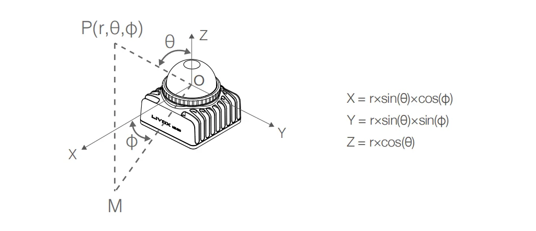
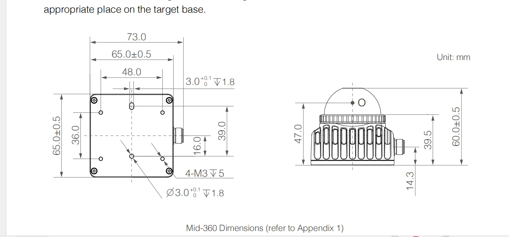
As shown above, the origin is on the LiDAR’s central axis, 47 mm above its bottom surface.
In other words
底部安装面中心
    │
    │ +47 mm
    ↓
   O 点
First measure from the chassis or gimbal coordinate origin to the center of the Mid360 bottom mounting surface. Add 47 mm along Z to obtain the position of the official Mid360 O point relative to the chassis or gimbal.
Official explanation:
The official manual explicitly defines Mid-360’s O-XYZ as the point cloud coordinate frame, with O as its origin.
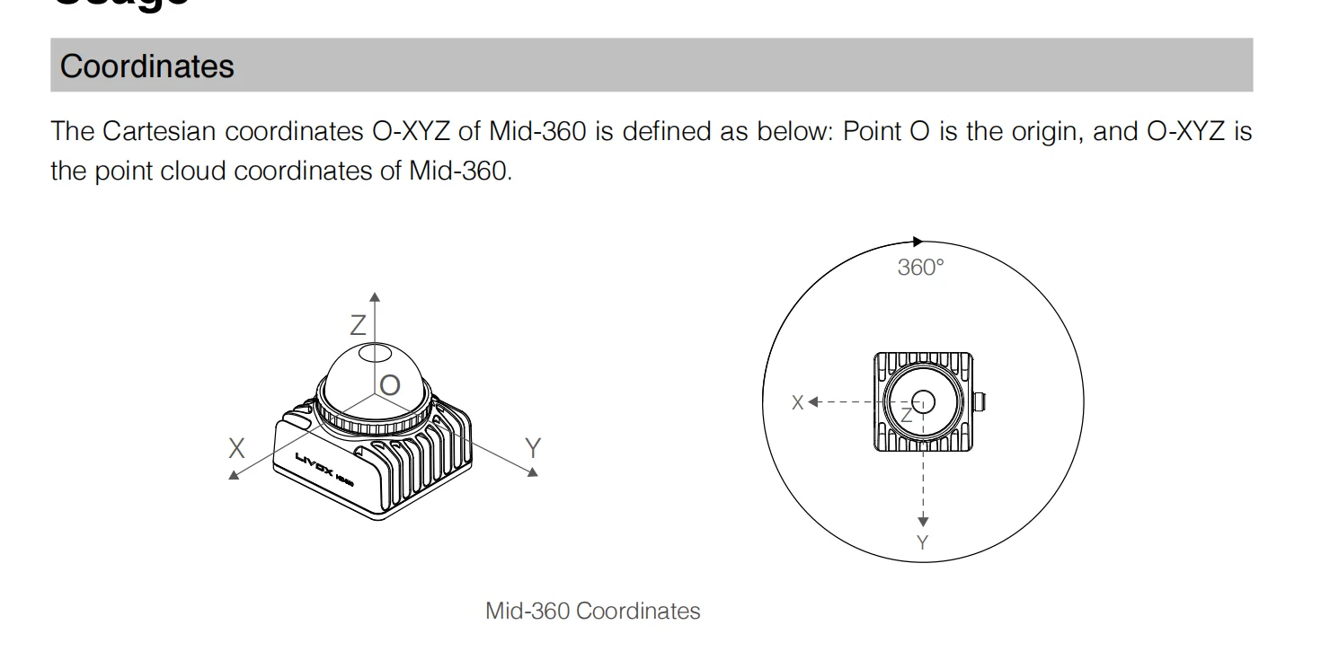
The built-in IMU chip’s position relative to this point cloud frame is:
x = +11.00 mm
y = +23.29 mm
z = -44.12 mm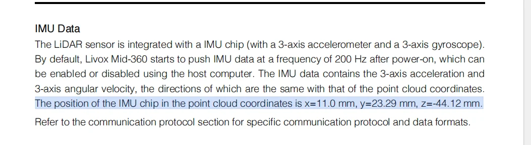
front_mid360 = LiDAR 点云 O 点
        ●
        │
        │  (+11, +23.29, -44.12) mm
        │
        ● IMU 芯片原点
To clarify in advance, front_mid360 is the LiDAR’s O_XYZ origin. The derivation is explained below.
- The mid360 pose
<!--livox--> <xmacro_block name="livox" prefix="front_" parent="chassis" pose="0.16 0.0 0.18 ${pi/6} 0.0 ${pi/2}" ... />- This pose is: chassis frame → front_mid360 frame
- In the Polar Bear configuration, it is strictly relative to the chassis origin.
- Its LiDAR is mounted on the chassis, so
parent="chassis"; to mount the LiDAR on the gimbal, change it toparent="gimbal_yaw". The offset then becomes relative to thegimbal_yawframe.
x = +0.16 m
y =  0
z = +0.18 m
This gives the Mid360 O origin relative to the chassis origin:
向前 160 mm
左右不偏
向上 180 mm
The last three pose parameters are RPY, the angular offsets relative to the chassis origin:
roll  = π/6 = 30°
pitch = 0°
yaw   = π/2 = 90°
Measurement shows only a 40-degree roll offset, namely
${2*pi/9}You will also see this in the Mid360 model:
<visual>
    <pose>0 0 0 0 0 ${pi}</pose>
This only rotates the visual mesh by 180°. It does not rotate the LiDAR sensor frame by 180°. Do not use it to calculate TF.
- Which point on the mid360 housing should be measured?
One further distinction is needed. The current Polar Bear Mid360 model contains:
<joint ...>
    <child>${prefix}mid360</child>
</joint>

<link name="${prefix}mid360">
Here,
${prefix}mid360is resolved tofront_mid360:This
front_mid360was confusing: what exactly is it? The readme describes the simulation as simplified, so do not infer this coordinate origin from the simulation. In reality’s Point LIO configuration, you can seeextrinsic_T: [-0.011, -0.02329, 0.04412]. This is precisely the official IMU offset. Also,frame_id = front_mid360. Therefore, working backward,front_mid360is our point cloud frame, namely O_XYZ.The Polar Bear LiDAR optical or scanning sensor also has an additional:
<sensor name="${prefix}mid360_lidar" ...>
<pose>0 0 0.03 0 0 0</pose>
front_mid360 link 原点 │ │ +30 mm ▼ LiDAR 扫描原点For the IMU:
<sensor name="${prefix}mid360_imu" type="imu">There is no additional pose, so in the current simulation the IMU origin essentially coincides with the front_mid360 origin.
- Which values should ultimately be entered for mid360?
front_mid360is the origin of the mid360 O_XYZ frame.The official Mid360 point cloud origin therefore coincides with the O_XYZ origin. The official Mid360 IMU origin is offset from O_XYZ by (+11, +23.29, -44.12) mm. However, there is no need to specify a pose here; specify it in point_lio instead.
Therefore
<!-- chassis -> Mid360 官方点云 O -->
<xmacro_block
    name="livox"
    prefix="front_"
    parent="chassis"
    pose="实际 x 实际 y 实际 z 实际 roll 实际 pitch 实际 yaw"
/>
Inside the Mid360 simulation:
<sensor name="${prefix}mid360_lidar" type="gpu_lidar">
<pose>0 0 0 0 0 0</pose>
I now understand the Polar Bear IMU arrangement: it directly aligns the IMU frame with the point cloud frame, and they also coincide in simulation. In reality, it uses
extrinsic_T: [-0.011, -0.02329, 0.04412]. This clearly accounts for the offset already, so we do not need to change the IMU frame offset.
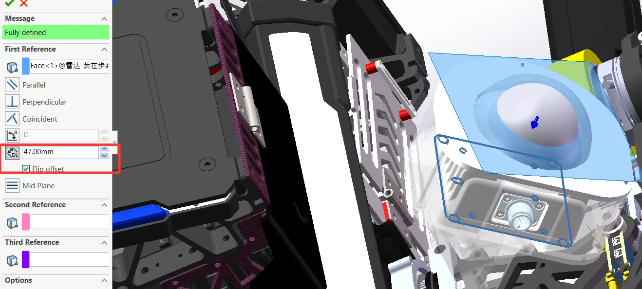
First, make a reference datum plane parallel to the bottom face.
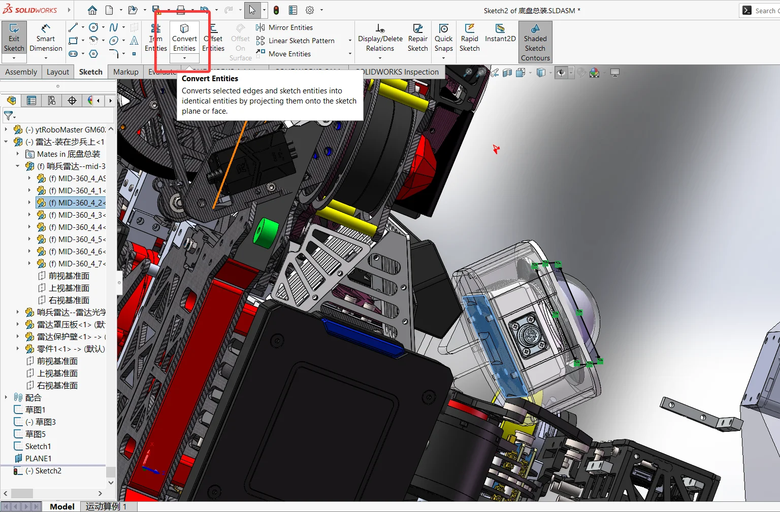
Then create a sketch based on this face, then click the bottom face and click Convert Entities.
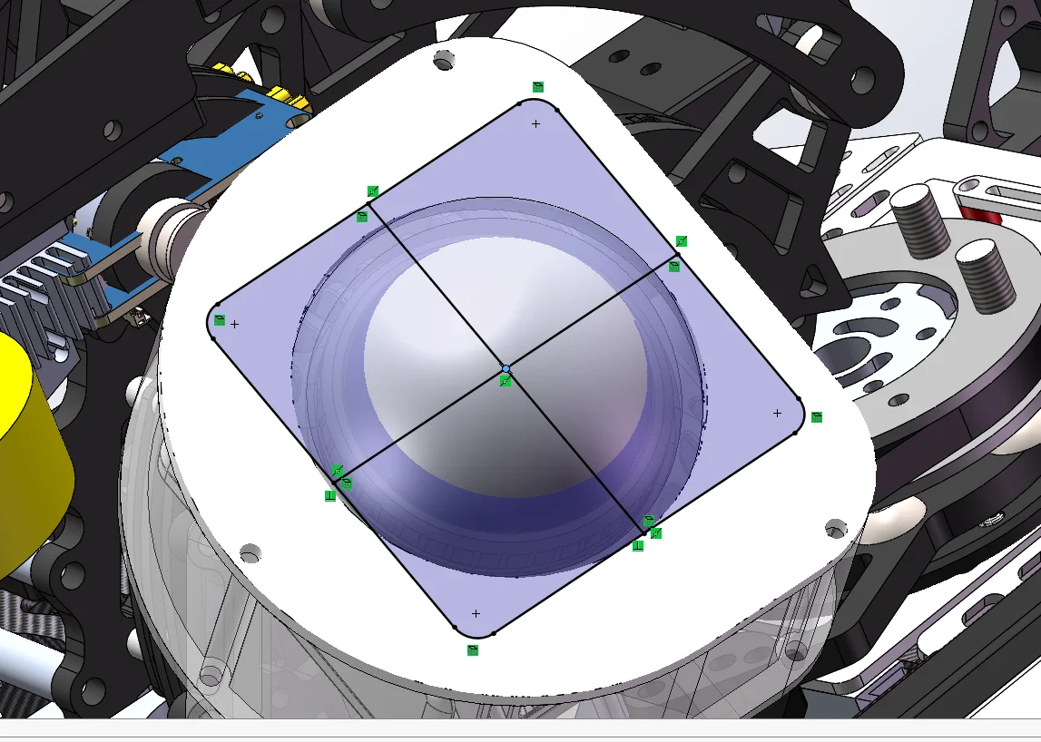
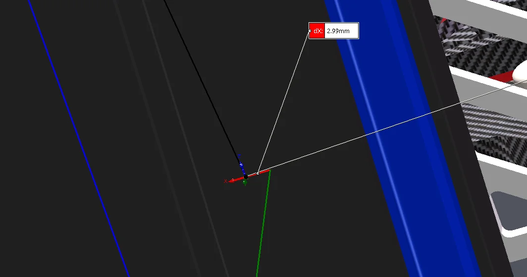
Mark the midpoint on this face. (This point is the point cloud OXYZ point.)
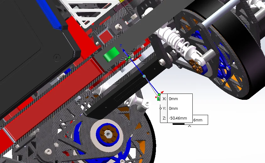
Then measure the distance from the point cloud OXYZ point to the center point of the base plate (the midpoint of the wheel axle).
As shown in the figure, offset backward by X=-2.99mm, offset to the left by Y=104.69mm, and offset upward by Z=255.58mm + 50.46mm = 306.04mm
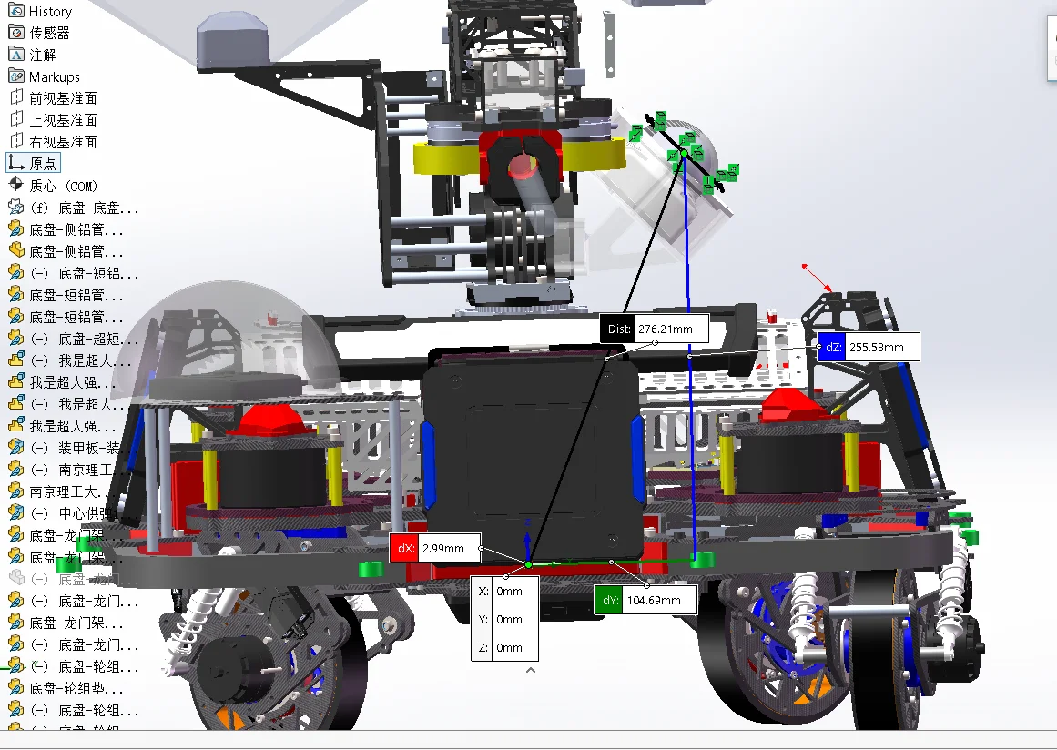
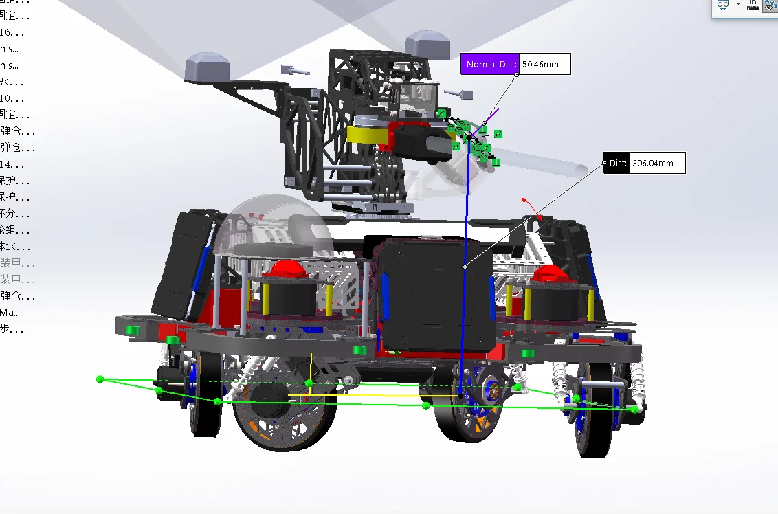
然后横滚偏roll = 45°,deg2rad = 0.25pi 然后航向角偏yaw = 180°,deg2rad = pi
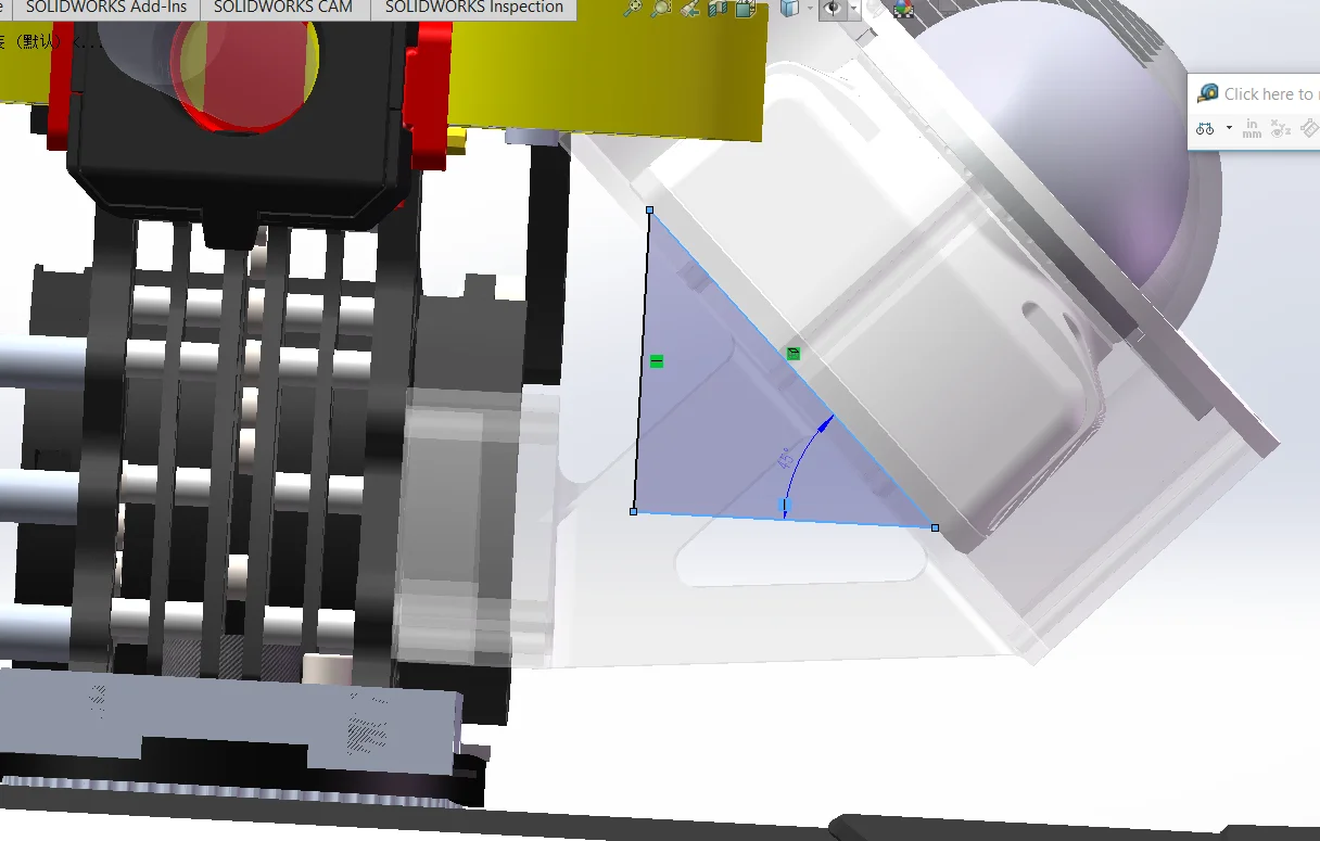
That is not all. The previous measurement was only the distance to the chassis, but we are actually mounted on the gimbal yaw, so z must subtract the distance from the chassis to the gimbal yaw. Therefore, the final upward offset z = 255.58mm + 50.46mm - 210.46mm = 95.58mm
        <!--livox-->
        <xmacro_block name="livox" prefix="front_" parent="gimbal_yaw" pose="-0.00299 0.10469 0.30604 ${pi/4} 0 ${pi}" update_rate="20" samples="1875"/>
In summary, the data you should need is:
1. 轮子实际直径

2. 前后轮中心轴距
   前轮中心 → 后轮中心

3. 左右轮中心轮距
   左轮中心面 → 右轮中心面

4. chassis 刚性主体:
   X 方向长度
   Y 方向宽度
   Z 方向高度

5. chassis/轮轴中心 → 云台 yaw 旋转轴中心:
   Δx
   Δy
   Δz

   如果云台不在底盘正中央,x/y 也得知道。

6. yaw 旋转轴中心 → 云台 pitch 旋转轴中心:
   Δx
   Δy
   Δz

7. Mid360 如果挂 chassis:
   chassis 原点 → Mid360 reference frame(mid360的原点:距离底面中心高47mm处)
   Δx Δy Δz
   roll pitch yaw

   如果挂 gimbal_yaw:
   yaw 轴原点 → Mid360 reference frame(mid360的原点:距离底面中心高47mm处)
   Δx Δy Δz
   roll pitch yaw
After modification:
chmod +x ./src/rmoss_gz_resources/update_model.sh
./src/rmoss_gz_resources/update_model.sh