Wiki
sensor_scan_generation(雷达点云换系与底盘、云台位姿转换)
Existing English translations were reused. 18 current source blocks remain in Simplified Chinese, without triggering paid translation.
1.sensor_scan_generation(雷达点云换系与底盘、云台位姿转换)
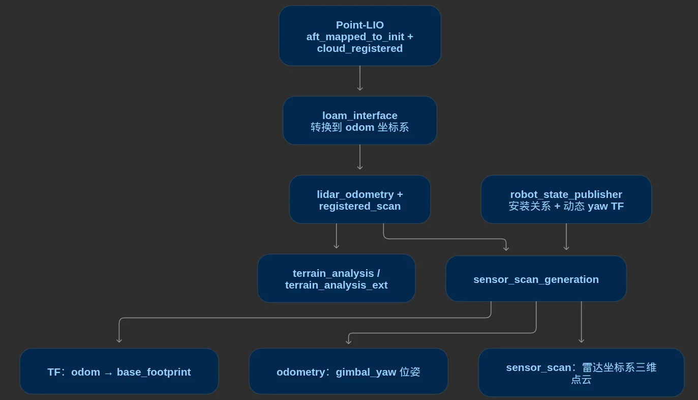
This node approximately pairs the radar pose output by loam_interface with the registered point cloud, and then combines them with the robot's mechanical TF to publish the chassis TF, the odometry in the specified frame, and the scan point cloud in the radar frame. Currently, the child frame of the chassis TF is base_footprint and the odometry child frame of the message is gimbal_yaw. The two serve different purposes.
The following checks use the source code and hardware YAML. These transformations require the upstream input to be an actual LiDAR pose. The internal IMU and LiDAR pose interface gap recorded above still affects this node and cannot be fixed here by renaming coordinate frames.
1.1.参数
1.1.1.ros__parameters (ROS node parameters)
1.1.1.1.Parameter table
sensor_scan_generation:
  ros__parameters:
    use_sim_time: False
    lidar_frame: "front_mid360"
    base_frame: "base_footprint"
robot_base_frame: "gimbal_yaw"| Parameter | Current value | Units | Hardware guidance | Purpose | Effect of increasing | Effect of decreasing | Activation conditions / notes |
|---|---|---|---|---|---|---|---|
use_sim_time |
False |
Not applicable; boolean | Verify and configure correctly before running on hardware | Select the time source for the node and TF buffer | Not applicable | Not applicable | Standard ROS2 parameter; usually False on hardware, True in simulation with /clock; the complete launch overrides the YAML value. Velocity differencing still uses steady_clock and does not switch with this setting |
lidar_frame |
"front_mid360" |
Not applicable; frame name | Verify and configure correctly before running on hardware | Specify the target LiDAR frame for mechanical TF queries and the reference frame of output sensor_scan messages |
Not applicable | Not applicable | Input lidar_odometry must actually describe that LiDAR pose. For every matched pair, use point cloud time to query LiDAR←chassis and LiDAR←specified body frame. This is not the internal IMU frame name |
base_frame |
"base_footprint" |
Not applicable; frame name | Verify and configure correctly before running on hardware | Specify the chassis pose transformation target and the child frame of the published TF | Not applicable | Not applicable | Currently publishes TF from the input odometry reference frame to base_footprint; does not determine the child frame of odometry or automatically zero z, roll or pitch. The standalone launch defaults to chassis |
robot_base_frame |
"gimbal_yaw" |
Not applicable; frame name | Verify and configure correctly before running on hardware | Specify the body frame and pose transformation for output odometry messages |
Not applicable | Not applicable | The current odometry describes the yaw gimbal layer, including gimbal yaw relative to the chassis. It does not separately broadcast reference-frame→gimbal_yaw TF; timing and coordinate expression of velocity fields have source-code concerns |
All four parameters are used; none in this section is entirely unused in the current execution path. The three frame parameters are read only during construction, so updating parameters with the same names at runtime does not update the member values. Applying later changes requires a separately authorized restart. Frame names are not numerical tuning parameters; increasing or decreasing them is not applicable.
1.1.1.2.Parameter Details
1.1.1.2.1.use_sim_time (system time and simulation time selection)
False uses system time; True uses ROS time from /clock . Input poses, registered scans, mechanical JointState and TF, and the node should share a consistent time domain. Otherwise, mechanical TF queries at message timestamps may fail.
This switch affects the node and TF cache clock, but the source code uses std::chrono::steady_clock separately when calculating velocity. So True will not make velocity automatically calculated according to simulation time, nor will it fix the input point time unit or clock synchronization issues.
1.1.1.2.2.lidar_frame (target radar coordinate system for scanning point cloud)
| Direction | Topic / TF | Current message and coordinate semantics |
|---|---|---|
| Subscribe | lidar_odometry |
nav_msgs/msg/Odometry; obtains the LiDAR pose in the input reference frame from the pose fields, expected to be expressed in odom for front_mid360 |
| Subscribe | registered_scan |
sensor_msgs/msg/PointCloud2; expected to be a registered scan in the same reference frame, odom for the points |
| Publish | sensor_scan |
PointCloud2; applies the inverse input LiDAR pose to transform point coordinates back into front_mid360 |
| Publish | odometry |
Odometry; retains the input odometry reference frame, header.frame_id, and sets the child frame to gimbal_yaw |
| Broadcast | Currently odom → base_footprint |
Retains the input odometry parent frame, header.frame_id, with the child frame specified by base_frame as the frame parameter |
Input and output topic names are fixed as relative names in the source code and may be affected by the node namespace or remapping; this block has no topic name parameters, and no odom_frame parameter. Coordinate frame strings do not automatically have the node namespace added.
sensor_scanThis is the result of converting the registered scan back to the radar frame; it will not recover points that have already been discarded by Point-LIO, nor does it perform new estimation or motion compensation. Positions and point coordinates continue to use m, orientations are dimensionless quaternions, the linear velocity field is expressed according to m/s, and the angular velocity field according to rad/s; the meaning of the velocities still needs to be determined in conjunction with the source code gap described below.
The node directly treats the input pose as the radar pose and uses its inverse transform to process the point cloud; it does not verify whether the input child_frame_id corresponds to lidar_frame nor does it verify that the reference frames of the two inputs are consistent. If the upstream is still the internal IMU pose, the mechanical TF from radar to chassis cannot replace the missing IMU-to-radar extrinsics.
1.1.1.2.3.base_frame (target frame of the chassis pose TF)
Each pairing callback queries by point cloud timestamp front_mid360 ← base_footprint, with a maximum wait of 0.5 seconds, not using the one-time initialization cache of upstream nodes. Let T_AB transform coordinates from frame B to frame A; O is the input odometry reference frame, L is the lidar, and B is the chassis. Then compute:
Currently broadcast through this result odom → base_footprint. When the chassis is stationary and only the actual yaw rotation occurs, the correct radar pose and the mechanical relative yaw should cancel each other out, resulting in a chassis pose that remains essentially stationary; this is the transformation target to be verified, and this test was not conducted in this round.
In the current model, base_footprint → chassis is a fixed connection, with a height of chassis_height=0.0625 m. This node retains the complete three-dimensional transformation and does not project the chassis onto the ground or force it to be horizontal based on its name.
Both mechanical TF queries pass getTransform; failure of either one will trigger an alarm and return an identity transform, while the callback still continues publishing. For example, if the radar→chassis query fails, the chassis pose will directly become the input radar pose, and the mounting offset and joint rotation are not deducted. Having output does not prove that the mechanical TF query succeeded.
1.1.1.2.4.robot_base_frame (coordinate system of the output gimbal-layer odometry)
Each callback also queries by point cloud time front_mid360 ← gimbal_yawand then computes:
R is robot_base_frame. This pose is written into odometry; therefore, the current message represents the origin and pose of the yaw gimbal layer. Although the publisher variable in the source code is named pub_chassis_odometry_, the actual child frame is robot_base_frame; it cannot be regarded as chassis odometry based on the variable name.
The MID360 is fixed at gimbal_yaw. The installation relationship from the LiDAR to the yaw gimbal layer is fixed; the LiDAR-to-chassis relationship includes the actual mechanical yaw and varies with the joint angle. The actual pitch is at gimbal_pitch_joint. It is located after the LiDAR mounting layer and should not enter the mechanical transformation from the LiDAR to these two target frames. The two odom joints remain fixed, and JointState continues to use {relative_pitch, relative_yaw, 0, 0}.
Current fake_vel_transform is also configured as subscription odometry and uses gimbal_yaw; the two names match.robot_base_frame determines the body frame expressed by the odometry message; it does not separately publish the TF for that body frame; the existing robot TF chain connects base_footprint to gimbal_yaw. The angular motion of the gimbal's independent yaw cannot be directly treated as the chassis angular motion.
1.1.1.2.5.Source Code Doubts Regarding Synchronization and Speed Calculation
Both subscriptions use Best Effort, Keep Last depth 1; the approximate time synchronizer's ApproximateTime(100) internal queue length is 100; both publisher queue depths are 2. These are written in the source code, with no corresponding YAML parameters; 100 is not an output frequency or a 100 ms tolerance.
Both inputs must form a pair before entering the publish callback. The source code does not set a maximum pairing time difference, nor does it interpolate the input pose to the point cloud time: the pose is taken from the paired odometry message, the mechanical TF is queried at the point cloud time, and the output TF and odometry are both marked with the point cloud time. Approximate pairing is not equivalent to the same sampling instant; the actual pairing error and motion effects still need to be verified.
Velocity is calculated by differencing two consecutive transformed robot_base_frame poses, without using the input odometry’s twist field. Three clear implementation problems must be recorded:
- Time base: The denominator is actual monotonic elapsed time between publication callbacks, rather than the difference between message timestamps. Simulation speed changes, pauses or callback backlogs may distort the differenced velocity;
use_sim_time=Truedoes not change this calculation path. - Coordinate expression: Position differences are calculated in the input reference frame, currently
odom. Orientation differences useq_current × q_previous.inverse()and are also expressed in that frame. Before writingtwist, no transformation intogimbal_yawis performed. However, the ROS Odometry definitionrequires velocity to be expressed inchild_frame_id; the current implementation violates the message convention. - First-frame handling: There is no flag indicating that a valid previous pose has been received, so even the first frame enters differencing.
previous_transformis not initialized from the first pose, and the initialprevious_timeis separated from the current time by only a short interval. The first velocity result may be abnormal and cannot be treated as a valid measurement.
The output pose and velocity covariances both remain at their default zero values; the source code does not estimate uncertainty. The above implementation issues can be confirmed from the source code; the actual velocity error, first-frame values, and impact on downstream were not measured by running in this round.
1.1.1.2.6.Startup configuration source
| Launch method | Parameter source | Differences relevant to this section |
|---|---|---|
| Complete reality launch | Defaults to pb2025_nav_bringup/config/reality/nav2_params.yaml; an alternative can be specified using params_file and loaded through navigation_launch.py as the configuration |
The three frame parameters match this table; use_sim_time is overridden by launch, defaulting to False |
| Complete simulation launch | Defaults to pb2025_nav_bringup/config/simulation/nav2_params.yaml; also loaded through navigation_launch.py as the configuration |
The three frame parameters match hardware; use_sim_time is overridden by launch, defaulting to True |
Standalone sensor_scan_generation.launch.py |
Reads its own declared lidar_frame/base_frame/robot_base_frame launch argument instead of the YAML above |
The respective defaults are front_mid360/chassis/gimbal_yaw; no use_sim_time launch argument is set or declared, so ROS2 defaults to False |
Independent default base_frame=chassis differs from the current full set configuration. If the current robot_state_publisher is also running, there is already a fixed base_footprint → chassis; publishing odom → chassis again would cause releases with different parents to appear in the same subseries; the independent default value cannot be directly regarded as equivalent to launching the full set.
The independently launched processes and component mode of the entire startup use the same processed parameter file,slamdoes not skip this interface. In this round, only the environment is loaded and the package path is queried in ysu_ros_humble to confirm that the installed launch of this package, the navigation launch, and the two YAML files are consistent with the current source code; no nodes were started, and the effective parameters of the running nodes were not read.
1.1.1.2.7.Observed and To Be Verified Items
- Confirmed from the source code: All four parameters are used; chassis TF differs from yaw-gimbal odometry; mechanical TF is queried at every point cloud timestamp; TF failures retain the identity transform; pairing is approximate; velocity has timing, coordinate and first-frame problems.
- Observed in simulation: The stationary and roughly 20 cm back-and-forth checks on 2026-10-08 covered standalone Point-LIO output, without verifying this node’s
sensor_scan, chassis TF, gimbal-layer odometry or differenced velocity. They cannot establish that this interface is correct. - Requires hardware verification: LiDAR and gimbal mounting extrinsics, mechanical relative yaw zero position, direction and radian units, clock consistency between joint and LiDAR data, and the full upstream transformation from internal IMU pose to LiDAR pose. When later testing is authorized, distinguish chassis motion, independent yaw and independent pitch, checking each output separately. Gravity direction and the simulation point-time interface remain pending verification.
1.2.实际问题与解决方案
已确认的直接故障:
sensor_scan_generation::getTransform() 在 TF 查询失败时返回单位变换,调用者仍把这个结果用于发布 odom → base_footprint。当用于雷达至底盘的查询失败时,发布的底盘位姿接近直接复制雷达位姿,丢掉雷达到底盘的安装旋转与平移。TF 查询恢复时则重新执行正常转换,因此出现突然腾空、倾斜,随后落回原位置的间歇性跳变。
| 分类 | 数量 |
|---|---|
| 正常转换 | 4014 |
| 与复制雷达位姿相符的单位变换回退 | 301 |
| 未归入上述两类 | 81 |
| 回退同时匹配到相同请求时刻的 TF 失败日志 | 301 |
| 记录窗口内 TF 失败日志总数 | 317 |
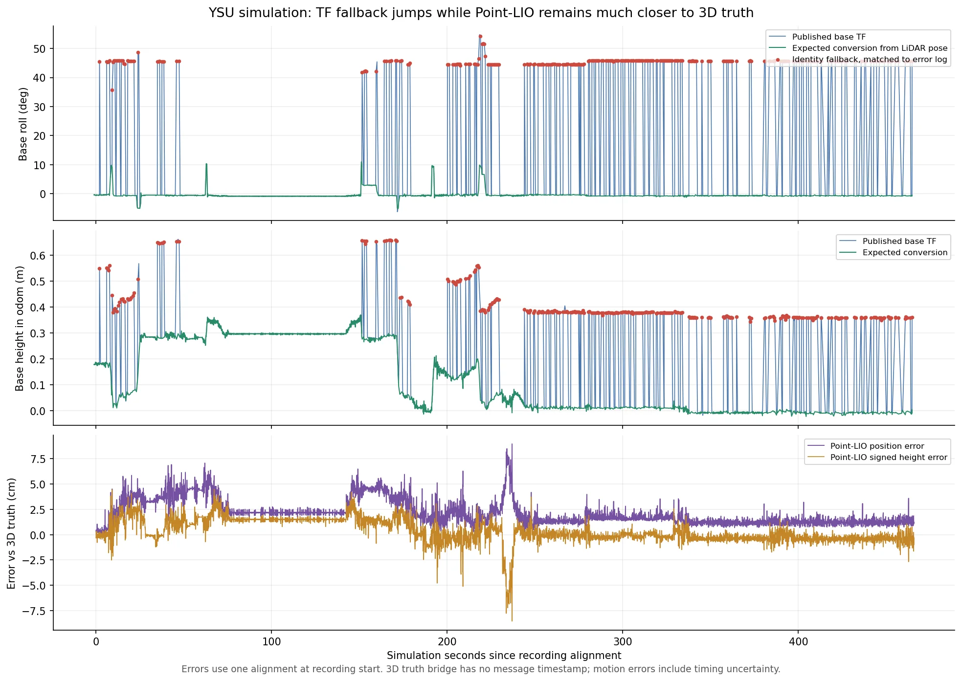
| 状态 | 底盘 TF 高度 | roll |
|---|---|---|
| 正常 | 0.18 米 | −0.5° |
| 查询失败 | 0.55 米 | 45.6° |
| 恢复 | 0.18 米 | −0.5° |
| 检查项 | 结果及含义 |
|---|---|
| 当前运行状态 | 仿真、Point-LIO、loam_interface、sensor_scan_generation 均存在,使用域 6 |
| 实际关节 TF 频率 | robot_state_publisher 是 20 Hz;当前 yaw TF 时间间隔主要为 50 ms |
| TF 接收线程 | 监听器有独立线程,不能简单认定为“回调等待时无人接收 TF” |
| 历史失败类型 | 检查开始时日志已有 378 次失败,全部是向未来查询 |
| 里程计发布量 | 当前开启逐点组发布;约 8 秒观察收到 12,706 条雷达里程计、125 帧扫描,约每帧对应 100 条里程计 |
它读取的主要话题是:
| 话题 | 类型 | 内容与来源 |
|---|---|---|
lidar_odometry |
nav_msgs/Odometry |
雷达在 odom 中的位姿,由 loam_interface 发布 |
registered_scan |
sensor_msgs/PointCloud2 |
已转换到 odom 坐标系的点云,由 loam_interface 发布 |
tf、tf_static |
tf2_msgs/TFMessage |
机器人安装关系和动态关节变换 |
/clock |
rosgraph_msgs/Clock |
启用仿真时间时使用的时钟 |
它将前两个话题按时间近似配对,然后以点云时间戳查询安装关系。
| 话题 | 内容 |
|---|---|
tf |
odom → base_footprint:通过雷达位姿和当时的云台 yaw,反推出底盘位姿 |
odometry |
odom 中的 gimbal_yaw 位姿,以及差分计算的速度;当前配置下不是底盘中心的里程计 |
sensor_scan |
转换到 front_mid360 坐标系的三维点云,类型仍是 PointCloud2,不是二维 LaserScan |
准确地说,故障顺序是:
- sensor_scan_generation 查询扫描时刻的雷达到底盘变换失败,这条关系包含动态云台 yaw。
- 代码用单位变换代替,继续计算并发布 odom → base_footprint。
- 底盘位姿因此近似变成雷达位姿,带上雷达的安装高度和约 45° 安装倾角。
- 查询恢复后,底盘 TF 又恢复正常。 查询失败的是雷达与底盘之间的变换;最终“炸掉”的输出是 odom → base_footprint。